Bluetooth Control of Timer and Cooler
To control the Arduino in the camera via Bluetooth, the Arduino must be equipped with a small serial Bluetooth module. Communication can also take place via a serial cable connection, but this is not very convenient.
The baud rate for communication between the Bluetooth module and Arduino is preset to 9600, which is also preconfigured for an HC-05 or DX-BT04. That's not great, but it's sufficient. What I reconfigure on the Bluetooth module is the name under which it responds, e.g. ‘2000Daci’.
To configure and operate the Arduino via a smartphone or tablet, you need an app that communicates with Bluetooth devices. You could put together your own app for this with a manageable amount of effort, but for now I chose the ‘Serial Bluetooth Terminal’, a very nice app that does exactly what I need for this application.
The Bluetooth code on the Arduino side is part of the ShutterEmuEOS program and can be easily adapted if necessary.
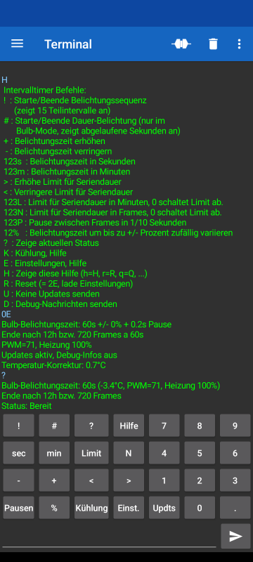
This screen shot of the 'Serial Bluetooth Terminal' app shows the output of the help function, the current settings and the status of the camera in the upper half.
In the lower part, the Bluetooth terminal offers a configurable ‘keypad’. Behind each button is a macro that can be customised. The macros are designed to send one character each to execute the most important commands directly. Some commands expect a sequence of digits to be entered before the command character.
The button configuration can also be exported to a file for editing on the computer or importing to other devices. A copy of this is included with the ShutterEmuEOS programme as
‘serial_bluetooth_terminal_cfg_astroshoot.txt’.
The commands for the interval timer, which triggers image series with freely selectable exposure times (and pauses), are located on the left-hand side of the keypad. The camera can be operated in bulb mode as well as in all other modes in which the camera specifies the exposure time, for example to record time-lapse series.
At the bottom there is also the ‘Kühlung’ button, which is used to send the instructions for setting the cooling (and easily could be renamed to 'Cooling'). For example, the character string ‘1K’, which is sent with the ‘1’ and ‘Kühlung’ buttons, switches the cooling to the lowest level, while ‘8K’ activates the PID controller, which keeps the temperature constant.
The current settings can be stored in the Arduino's EEPROM so that they are not lost when the camera is turned off.
Help and Info
Interval Timer
The interval timer can trigger the camera periodically. For long exposures, the mode has to be selected and the interval timer determines the exposure time.
If the exposure time is to be specified by the camera, the interval timer is set to the short-term value of 0.1 seconds by repeatedly entering '–' and then triggers ten times per second (short exposures).
H : Show help overview
K, E, F, A : Show help for individual command groups
? : View the current status of cooling and exposure
U : Turn ongoing status updates off or on
D : Toggle display of debug messages on or off
Interval Timer
The interval timer can trigger the camera periodically. For long exposures, the mode has to be selected and the interval timer determines the exposure time.
If the exposure time is to be specified by the camera, the interval timer is set to the short-term value of 0.1 seconds by repeatedly entering '–' and then triggers ten times per second (short exposures).
Start/Stop:
! : Start the exposure sequence with the selected time and duration.
Enter again to end the sequence. A current exposure is still being completed. Meanwhile, the sequence can be resumed by sending ‘!’ again.
If a shutter emulator is running in parallel, the timer receives the exact trigger time from it and relates the selected exposure time to this (see also pauses).For bulb exposures, the progress of each exposure is indicated by a sequence of 16 stars. If the camera does not respond to triggers, a message is displayed.
If three consecutive shutter releases are missing after registered shutter releases, e.g. because the memory card is full, the interval timer stops and switches off the cooling to avoid fogging up the unused, cold sensor.For short exposures a dot is output every second, shutter releases are indicated by apostrophes.# : Starts a continuous exposure or cancels ongoing exposures (immediately).Shows progress in seconds.
? : Displays current status and exposure settings.
Exposure Time:
+ : Increase exposure time step by step. The predefined levels are
0.1s, 30s, 60s, 100s, 300s, 600s, 20min, 40min, 60min
– : Decrease exposure time step by step.
123s : Select exposure time in seconds.
123m : Specify exposure time in minutes.
123P : Specify the pause between two exposures in tenths of a second, 0 selects the default value.
By choosing an extended pause between shutter releases, the exposure time can be precisely defined regardless of the delay caused by image storage, even if there is no shutter signal available (see above).
The default is a pause of 0.2 seconds, but this is extended by the camera if necessary. Without a shutter signal at the expense of the next exposure.If the pauses are too short, only every second exposure may start!
With long pauses also timelapse series can be recorded. To do this, the exposure time for the timer must be set to at least 1 second.
If the exposure time is specified by the camera, timelapse series can also be created simply by using long exposure times. (The camera will not shoot again until the timer completes the last exposure.)
n% : Vary exposure time randomly by up to +/-n percent.
Series Duration:
> : Increase the limit for the series duration step by step. The predefined limits are:
no limit, 16h, 12h, 8h, 6h, 4h, 2h, 1h, 30min, 20min, 10minWhen the maximum series duration has been reached, no further exposures are made and the cooling is switched off.
< : Decrease the limit for the series duration step by step.
123L : Specifies the limit for the series duration in minutes, 0 switches off the limit.
123N : Specifies the limit for the series duration as number of exposures, 0 switches off the limit.
Calculates the required time taking into account the selected pauses.
.
Recording of Exposures
The interval timer records a log of all exposures, which includes the sensor and, if available, the ambient temperature. The log can hold up to around 500 entries if it is stored in regular RAM.
If an external flash module is present, up to 10,000 entries are saved. In addition, the protocol is still available even after the camera was switched off. It is only deleted when another log is created and it can also be integrated into the new log.
Recording commands:
A : Display recording commands.
0A : Stops recording the exposures.
1A : Resumes a paused recording.
2A : Deletes the previous recording and restarts it.
3A : Displays the recording. With further 'A's the display can be paused.
4A : Adopts recordings that were already present when the camera was switched on as the
current recording, so that they are not deleted the first time additional records are taken.
Cooling Control
The prerequisite for cooling control is a Peltier element, which is regulated via a PWM output of the Arduino, and a temperature sensor in thermal contact with the image sensor.
If available, the window heating is also integrated into the cooling control. The respective availability of the control loops and the pin assignment is defined together with the shutter emulation connections in camera.h (see the camera "MY_2000D_2" as an example).
If an ambient temperature and humidity sensor is available, the dew point is calculated and included in the control.
K : Display cooling commands.
0K : Turn off the cooling or, if not possible, at least turn it down to the lowest level.
1K..5K : Switches the cooling on between minimum (1) and maximum strength (5).
1nnnK : Operates the cooling with the PWM signal nnn (= 000 to 255, exactly 3 digits).
Attention: Depending on the electrical circuit, both 0 or 255 can mean the highest cooling performance.
7K : Waits for a target temperature to be entered and starts the PID control to achieve it.
8K : Activates the PID control to preserve the current sensor temperature.
9K : Activates the PID control after 10 minutes to preserve the then measured temperature.
20K : Turns off the window heating.
21K..25K : Switches the window heating between minimum (1) and maximum strength (5).
29K : Includes the window heating in the dew point control.Dew Point Control:
If an ambient temperature and a humidity sensor (e.g. an AHT20) are installed, the dew point is calculated and displayed. Whether the dew point control is activated is indicated by a '~' sign after the PWM display. The default is 'activated' or the setting saved in the EEPROM.
When PID control is switched on, the dew point control adjusts the target temperature to the dew point. Without PID control, cooling capacity is reduced when the window temperature falls below the dew point.
The window temperature is estimated from the sensor temperature measurement by adding a correction value, which is entered with the 'T' command, to the sensor temperature measurement.
The dew point control can also be extended to window heating with the command '29K'. Then the window heating is increased or reduced when the window temperature is below or above the dew point.
10K : Deactivates the dew point control.
11K : Activates the dew point control.
29K : Includes the window heating in the dew point control.
Temperature Corrections
T : Enter temperature correction for sensor temperature, ambient temperature or dew point.
The correction values entered are added to the measured values and can be stored in the EEPROM of the Arduino. They are used to compensate for inaccuracies, for example due to the camera releasing heat onto the environmental sensors. For the dew point control, the window temperature is assumed as the sensor temperature plus the correction value.
PID Calibration
The PID control of the sensor temperature works quite reliably with the preset parameters. Nevertheless, the control parameters can be adjusted, either by directly entering other values or through automatic calibration, which usually produces poorer results.
0C : Show current PID coefficients.
1C : Reset the PID coefficients to their basic setting.
2C : Load PID coefficients stored in EEPROM.
3C : Save current PID coefficients to EEPROM.
4C : Delete saved PID coefficients from the EEPROM.
5C : Enter PID coefficients manually.
nnC : Automatically determine the PID coefficients.
To do this, the PWM signal is changed by “nn” (nn >= 10).
C : Cancel / end calibration.
After the end of the automatic calibration, the PID coefficients found are displayed and can be accepted or discarded.
Saving Settings in the EEPROM of the Arduino
To prevent the current settings from being lost when the camera is switched off, they can be saved in the Arduino's EEPROM:
E : Displays the settings commands below.
0E : Displays the current settings.
1E : Loads the basic settings that are used when nothing is stored in the EEPROM.
2E : Reloads the settings saved in the EEPROM. R : Resets the Arduino completely (Urboot/Optiboot required).
3E : Saves all current settings in the EEPROM.
4E : Deletes all settings stored in the EEPROM.
Software Updates via Bluetooth
If an external flash module is connected to the SPI interface of the Arduino, updates for the Arduino can be installed via it. In addition, a backup version can be stored, which is installed as an update by the Arduino's watchdog timer if the current program version is not responsive.
Update commands:
F : Display update commands.
1F : Expects the upload of a HEX file via Bluetooth (or serial interface), which is stored
in the external SPI flash starting at address 0x000000. The first two bytes, which the bootloader interprets as a request to install the following code, are removed and replaced by 0xFF, which blocks the update function.
2F : Adds the missing first two bytes and triggers a reset so that Urboot installs the code up
to 0x007FFF as an update. Enables watchdog monitoring (see below) for the possibility that the update does not work correctly and can no longer perform updates.
3F : Copies the upload area to the second half of the first page of the external flash (0x008000)
and adds the missing first two bytes. In the event of a watchdog interrupt, this backup version is copied to 0x000000 for installation as an update by the bootloader.
4F : Installs the backup version stored in the external Flash as an update.
0F : Enables or disables watchdog monitoring and saves this setting in EEPROM.
Watchdog monitoring is automatically activated when installing an update (with '2F'). However, it remains inactive if no backup version has been set up yet. It makes sense to switch it off as soon as you are sure that the last update can carry out further updates.
Test functions:
5F : Displays the beginning of the internal flash (0x0000) as a hex dump.
6F : Displays the beginning of the external flash (the upload buffer at 0x000000) as a hex dump.
7F : Show backup version in external flash (0x008000).
8F : Show area of the exposure log in the external flash.
9F : Runs an infinite loop to trigger the watchdog interrupt (after 4 seconds)
which should then install the backup version.
Entering additional command parameters
Some commands require an input value in floating point format, i.e. in the form "+/-1.2e-3". When prompted to enter, the commands tell a letter with which the entry must be completed so that the entry is considered completed and the value is assigned correctly.
Example: The command "7K" expects a target temperature for the PID controller, which must be completed with 'K' (for cooling). A valid entry would then be, for example:
"-2.5K"
or all together
"7K-2.5K"
Last updated on February 16, 2025